Dimension Guidelines Introduction to Engineering Design - ppt download
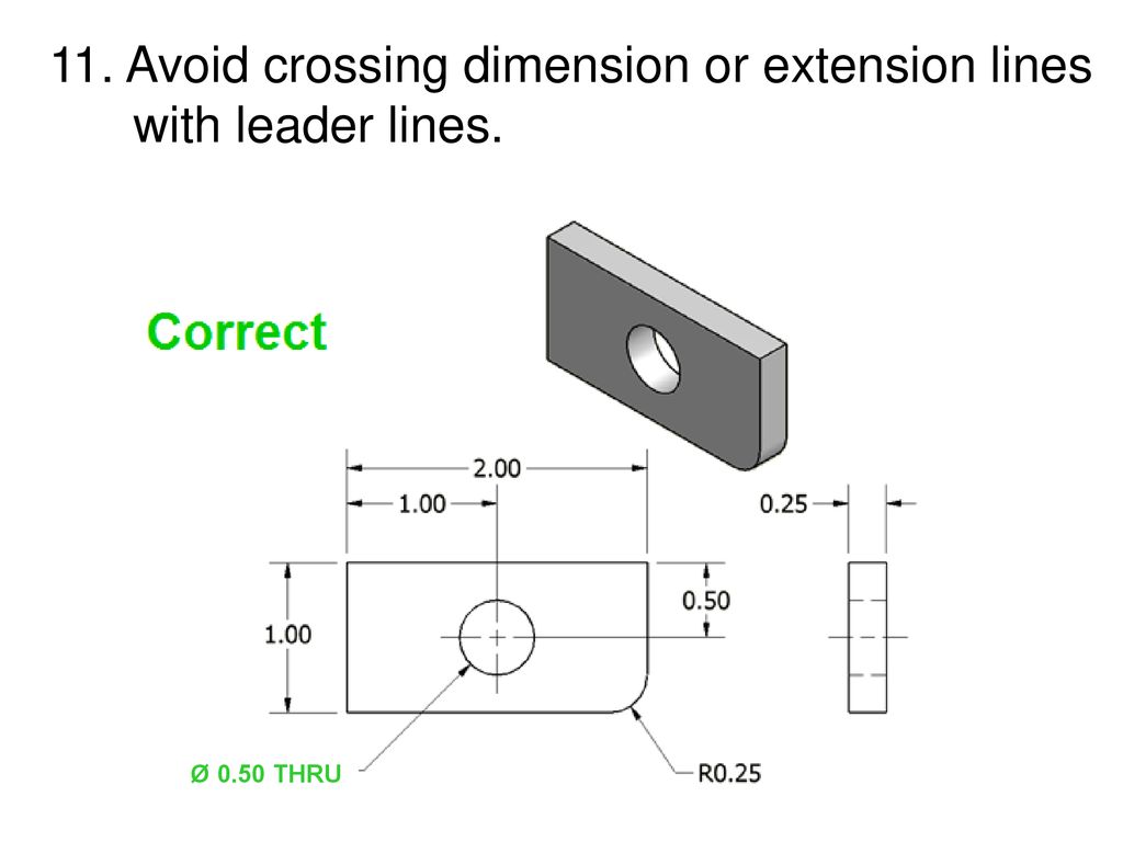
11. Avoid crossing dimension or extension lines with leader lines. Dimension Guidelines Introduction to Engineering Design Unit 2 – Lesson 2.2 – Dimensions and Tolerances 11. Avoid crossing dimension or extension lines with leader lines. References: Pg 342 Engineering Drawing and Design 3rd Edition by David Madsen et. al. Pg 394, 426 Technical Drawing 9th Edition by Frederick Giesecke et. al. Ø 0.50 THRU Project Lead The Way, Inc. Copyright 2007
11. Avoid crossing dimension or extension lines with leader lines. Incorrect. References: Pg 342 Engineering Drawing and Design 3rd Edition by David Madsen et. al. Pg 394, 426 Technical Drawing 9th Edition by Frederick Giesecke et. al. Project Lead The Way, Inc. Copyright
Dimension Guidelines. Introduction to Engineering Design. Unit 2 – Lesson 2.2 – Dimensions and Tolerances. 11. Avoid crossing dimension or extension lines with leader lines. References: Pg 342 Engineering Drawing and Design 3rd Edition by David Madsen et. al. Pg 394, 426 Technical Drawing 9th Edition by Frederick Giesecke et. al. Ø 0.50 THRU. Project Lead The Way, Inc. Copyright
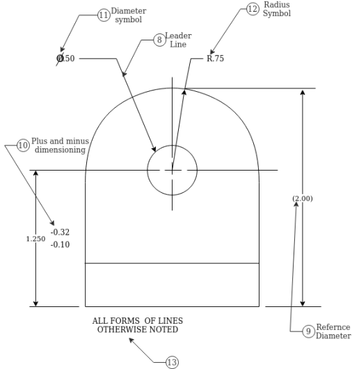
12. Leader lines point toward the center of the feature and should not occur horizontally or vertically. References: Pg 45, 344 Engineering Drawing and Design 3rd Edition by David Madsen et. al. Pg , , 426 Technical Drawing 9th Edition by Frederick Giesecke et. al. Pg , 703 Technical Graphics Communication 3rd Edition by Gary Bertoline & Eric Wiebe. Note: Slopes greater than 75° and less than 15° from horizontal should be avoided. A leader has a .25 in shoulder at one end that begins at the center of the vertical height of the lettering and an arrowhead at the other end point. Project Lead The Way, Inc. Copyright
13. Dimension numbers should be centered between arrowheads, except when using stacked dimensions, and then the numbers should be staggered. Incorrect. References: Pg Engineering Drawing and Design 3rd Edition by David Madsen et. al. Pg 137 Fundamentals of Modern Drafting by Paul Wallach. Pg 400, 426 Technical Drawing 9th Edition by Frederick Giesecke et. al. Pg Technical Graphics Communication 3rd Edition by Gary Bertoline & Eric Wiebe. Note: The 0.50 dimension cannot fit between its extension lines, so it is placed to the outside of the common extension line to avoid confusion. Project Lead The Way, Inc. Copyright
13. Dimension numbers should be centered between arrowheads, except when using stacked dimensions, and then the numbers should be staggered. References: Pg Engineering Drawing and Design 3rd Edition by David Madsen et. al. Pg 137 Fundamentals of Modern Drafting by Paul Wallach. Pg 400, 426 Technical Drawing 9th Edition by Frederick Giesecke et. al. Pg Technical Graphics Communication 3rd Edition by Gary Bertoline & Eric Wiebe. Project Lead The Way, Inc. Copyright
14. In general, a circle is dimensioned by its diameter and an arc by its radius. References: Pg , Engineering Drawing and Design 3rd Edition by David Madsen et. al. Pg 131, Fundamentals of Modern Drafting by Paul Wallach. Pg , , 427 Technical Drawing 9th Edition by Frederick Giesecke et. al. Pg , Technical Graphics Communication 3rd Edition by Gary Bertoline & Eric Wiebe. Project Lead The Way, Inc. Copyright
15. Holes should be located and sized in the view that shows the feature as a circle. Incorrect. References: Pg 351 Engineering Drawing and Design 3rd Edition by David Madsen et. al. Pg 109 Fundamentals of Modern Drafting by Paul Wallach. Pg 411, 427 Technical Drawing 9th Edition by Frederick Giesecke et. al. Pg 693 Technical Graphics Communication 3rd Edition by Gary Bertoline & Eric Wiebe. Project Lead The Way, Inc. Copyright
15. Holes should be located and sized in the view that shows the feature as a circle. References: Pg 351 Engineering Drawing and Design 3rd Edition by David Madsen et. al. Pg 109 Fundamentals of Modern Drafting by Paul Wallach. Pg 411, 427 Technical Drawing 9th Edition by Frederick Giesecke et. al. Pg 693 Technical Graphics Communication 3rd Edition by Gary Bertoline & Eric Wiebe. Note: The top view was removed because it is not needed to completely communicate the object’s geometry. Project Lead The Way, Inc. Copyright
16. Holes are located by their centerlines, which may be extended and used as extension lines. References: Pg 44, 340 Engineering Drawing and Design 3rd Edition by David Madsen et. al. Pg , 426 Technical Drawing 9th Edition by Frederick Giesecke et. al. Pg Technical Graphics Communication 3rd Edition by Gary Bertoline & Eric Wiebe. Project Lead The Way, Inc. Copyright
Giesecke, F. [et al.] (1991). Technical drawing. (9 ed.). New York, NY: Macmillan Pub. Co. Madsen, D., Folkestad, J., Schertz, K., Shumaker, T., Stark, C., & Turpin, J. (2002). Engineering drawing and design. (3 ed.). Albany, NY: Delmar Thomas Learning.
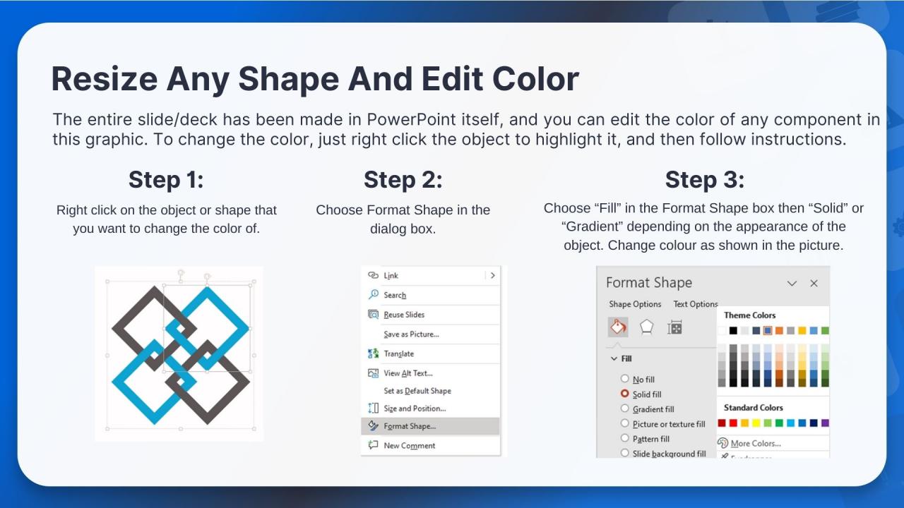
Advanced PowerPoint grids and guides

18 Creative Research Poster Templates (Word, PowerPoint) ᐅ

Engineering Drawing Overview & Basic Components - WayKen

SOLUTION: Introduction to Mechanical Engineering Design
.png)
20 Great Examples of PowerPoint Presentation Design [+ Templates]

The Easy Guide to Making a Business Plan Presentation
Best Software Development Life Cycle (SDLC) Models PowerPoint
Dimension Guidelines Introduction to Engineering Design - ppt download
PowerPoint Slide Sizes: How To Change & Manage Them Better

MQC On Mechanical Engineering - PowerPoint Slides - LearnPick India

Software Engineering PowerPoint Template - PPT Slides
Engineering Maintenance Powerpoint Ppt Template Bundles

Software Engineering Design Principles Ppt Powerpoint Presentation

Introduction to Engineering Design

28 Free Technology PowerPoint Templates for Amazing Presentations